Half-bridge sine wave inverter
Welcome to our dedicated page for Half-bridge sine wave inverter! Here, we have carefully selected a range of videos and relevant information about Half-bridge sine wave inverter, tailored to meet your interests and needs. Our services include high-quality hybrid electric systems, photovoltaic panels, and advanced inverters, designed to serve a global audience across diverse regions.
We proudly serve a global community of customers, with a strong presence in over 20 countries worldwide—including but not limited to the United States, Canada, Mexico, Brazil, the United Kingdom, France, Germany, Italy, Spain, the Netherlands, Australia, India, Japan, South Korea, China, Russia, South Africa, Egypt, Turkey, and Saudi Arabia.
Wherever you are, we're here to provide you with reliable content and services related to Half-bridge sine wave inverter, including cutting-edge hybrid electric systems, advanced photovoltaic panels, and tailored energy solutions for a variety of applications. Whether you're looking for residential hybrid installations, commercial energy projects, or off-grid power solutions, we have a solution for every need. Explore and discover what we have to offer!
SM72295 data sheet, product information and support | TI
SM72295EVM provides a highly integrated gate driver solution for wide Industrial applications such as 800VA to 3kVA Pure Sine Wave Inverter, Interleaved Buck or Boost SMPS, four
Email Contact
What is Half-Bridge Inverter? – Circuit Diagram & Working
In half-bridge inverters, only two thyristors are used to convert dc power into ac power, whereas in full-bridge inverters four thyristors are used. In this article, let us learn about
Email Contact
Design of Unipolar Pure Sine Wave Inverter with Spwm
In the Matlab simulation, the inverter can change the 12 vdc to 12 vpeak with a carrier signal of 20 khz and a reference signal of 50 hz. From the results of the inverter output will be changed to
Email Contact
Convert any H-Bridge Inverter to Sine Wave H-bridge
The following diagram shows a practical example of how an simple IRS2453 H-bridge inverter circuit can be converted into a sine wave H-Bridge
Email Contact
Simulation of SPWM Half-Bridge Sine wave inverter in Simulink...
In this tutorial video we have taught about design and simulation of SPWM based Half-Bridge Sine Wave inverter in Simulink. These are widely used in electricity conversion.
Email Contact
rohitshettigar/Design-and-Implementation-of-Single-Phase-Half-Bridge
This project involves designing and implementing a single-phase half-bridge sinusoidal PWM inverter using MOSFETs to generate a 9V, 50Hz AC output from a DC source.
Email Contact
A New SPWM Approach for High-Performance Single-Phase Half-Bridge
This paper presents the design and simulation of single-phase inverter using sinusoidal pulse width modulation (SPWM) unipolar technique.
Email Contact
Build and Simulate a Single-Phase Half-Bridge Inverter with Ideal
Build a Simscape Electrical model of a single-phase half-bridge inverter with ideal switches, run the model, and examine the results.
Email Contact
Single Phase Half Bridge Inverter | Circuit, operation and
Circuit Diagram Single Phase Half Bridge Inverter consists of two switches, two diodes called feedback diodes and three-wire supply.
Email Contact
Single-Phase Inverters
As depicted in Figure 1, the half-bridge inverter architecture is a basic single-phase inverter structure. It is made up of two switching components (usually transistors, IGBTs, or
Email Contact
H Bridge Inverter Circuit using IC SG3525 and
Conclusion The SG3525-based H-bridge inverter circuit is a reliable and efficient solution for converting DC voltage to AC power. With features
Email Contact
Single Phase Inverter
The half bridge inverter architecture serves as a fundamental building block in the realm of single phase inverters, offering a straight forward structure that efficiently converts
Email Contact
Full Bridge Inverter: Circuit, Waveforms, Working And
Power inverters are two types according to the characterization that is single-phase inverters and three-phase inverters. Single-phase inverters are
Email Contact
A New SPWM Approach for High-Performance Single-Phase Half
This paper presents the design and simulation of single-phase inverter using sinusoidal pulse width modulation (SPWM) unipolar technique.
Email Contact
Full Bridge Inverter – Circuit, Operation, Waveforms
What is a Full Bridge Inverter ? Full bridge inverter is a topology of H-bridge inverter used for converting DC power into AC power. The components
Email Contact
What is Half-Bridge Inverter? – Circuit Diagram
In half-bridge inverters, only two thyristors are used to convert dc power into ac power, whereas in full-bridge inverters four thyristors are used.
Email Contact
Inverter | PPTX | Internet of Things
The document is an introduction to power electronics focusing on inverter units, detailing the types of inverters including square wave, modified sine wave, and
Email Contact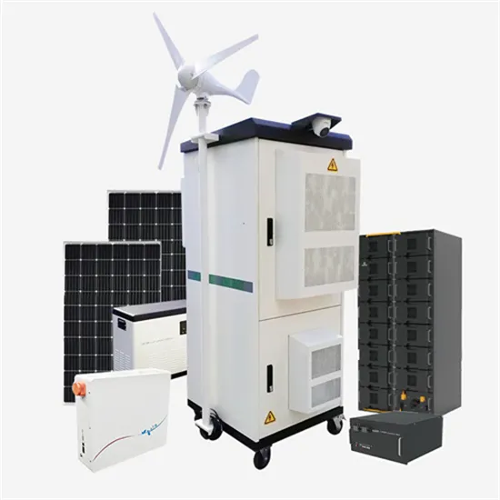
A New SPWM Approach for High-Performance Single-Phase Half-Bridge
A New SPWM Approach for High-Performance Single-Phase Half-Bridge Inverters with Pure Sine Wave. In: Bendaoud, M., El Fathi, A., Bakhsh, F.I., Pierluigi, S. (eds) Advances
Email Contact
Half Bridge Inverter : Circuit, Advantages, & Its Disadvantages
What is Half-Bridge Inverter? The inverter is a device that converts a dc voltage into ac voltage and it consists of four switches whereas half-bridge inverter requires two diodes and two
Email Contact
Half Bridge Inverter : Circuit, Advantages, & Its
8 rows· What is Half-Bridge Inverter? The inverter is a device that converts a dc voltage into ac voltage and it consists of four switches whereas half-bridge
Email Contact
Inverter Circuits – Homemade Circuit Projects
In this article I will explain how we can build an Arduino-controlled H-Bridge sine wave inverter circuit using some easy parts. So this thing will basically convert DC into AC but
Email Contact
Design a Half Bridge Inverter and a Full Bridge Inverter with
This paper presents design an inverter with overcurrent protection circuit without microcontroller, where the MOSFET gate driver is controlled by pulses generated from 555
Email Contact
SINGLE PHASE SINE WAVE PWM INVERTER
A single phase half bridge inverter with two MOSFET switches are used to convert the 12V DC into 230V AC.Two switches S1 and S2 are used to chop the DC supply and a transformer
Email Contact
rohitshettigar/Design-and-Implementation-of-Single-Phase-Half
This project involves designing and implementing a single-phase half-bridge sinusoidal PWM inverter using MOSFETs to generate a 9V, 50Hz AC output from a DC source.
Email Contact
Half H-Bridge Inverter – Circuit, Operation, Waveforms & Uses
What is Half H-Bridge Inverter? Half H-bridge is one of the inverter topologies which convert DC into AC. The typical Half-bridge circuit consists of two control switches, 3 wire DC supply, two
Email Contact